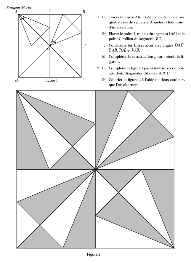
%@Auteur: François Meria\par
\begin{multicols}{2}
  \begin{center}
    \psset{unit=0.4cm}
    \pspicture(15,15)
    \pstGeonode[PointSymbol=none,PosAngle={235,-45,45,135,0,90}](0,0){D}(15,0){C}(15,15){B}(0,15){A}(15,7.5){J}(7.5,15){I}
    \pspolygon(A)(B)(C)(D)
    \pstInterLL[PointSymbol=none,PosAngle=-118]{A}{C}{B}{D}{O}
    \psline(A)(C)
    \psline(B)(D)
    \pstGeonode[PointSymbol=none,PointName=none](7.5,0){I1}(0,7.5){J1}
    \psline(J)(J1)
    \psline(I)(I1)
    \pstBissectBAC[linestyle=none,PointSymbol=none,PointName=none]{D}{A}{O}{M1}%
    \pstInterLL[PointName=none,PointSymbol=none]{A}{M1}{J}{O}{T1}%
    \psline(A)(T1)
    \pstBissectBAC[linestyle=none,PointSymbol=none,PointName=none]{O}{A}{B}{M2}%
    \pstInterLL[PointName=none,PointSymbol=none]{A}{M2}{I}{O}{T2}%
    \psline(A)(T2)
    \psline(T1)(T2)
    \pstMarkAngle[MarkAngleRadius=1.2]{T1}{A}{O}{}
    \pstMarkAngle[MarkAngleRadius=1.4]{T1}{A}{O}{}
    \pstMarkAngle[MarkAngleRadius=1.4]{O}{A}{T2}{}
    \pstMarkAngle[MarkAngleRadius=1.6]{O}{A}{T2}{}

    \pstBissectBAC[linestyle=none,PointSymbol=none,PointName=none]{B}{O}{I}{N1}%
    \pstInterLL[PointName=none,PointSymbol=none]{O}{N1}{I}{B}{P1}%
    \psline(O)(P1)
    \pstBissectBAC[linestyle=none,PointSymbol=none,PointName=none]{J}{O}{B}{N2}%
    \pstInterLL[PointName=none,PointSymbol=none]{O}{N2}{J}{B}{P2}%
    \psline(O)(P2)
    \psline(P1)(P2)
    \pstMarkAngle[MarkAngleRadius=1.2]{B}{O}{P1}{}
    \pstMarkAngle[MarkAngleRadius=1.4]{B}{O}{P1}{}
    \pstMarkAngle[MarkAngleRadius=1.4]{P2}{O}{B}{}
    \pstMarkAngle[MarkAngleRadius=1.6]{P2}{O}{B}{}
    % fin de la première partie de la construction
    \put(6.2,-1){Figure 1}
    \endpspicture
  \end{center}
  \par\columnbreak\par
  \begin{enumerate}[1.]
  \item
    \begin{enumerate}[(a)]
    \item Tracer un carré $ABCD$ de $15$~cm de côté et ses quatre axes
      de symétrie. Appeler $O$ leur point d'intersection.
    \item Placer le point $I$, milieu du segment $[AB]$ et le point
      $J$, milieu du segment $[BC]$.
    \item Construire les bissectrices des angles $\widehat{OAD}$,
      $\widehat{OAB}$, $\widehat{IOB}$ et $\widehat{JOB}$.
    \item Compléter la construction pour obtenir la figure 1.
    \end{enumerate}
  \item
    \begin{enumerate}[(a)]
    \item Compléter la figure 1 par symétrie par rapport aux deux
      diagonales du carré $ABCD$.
    \item Colorier la figure 2 à l'aide de deux couleurs que l'on
      alternera.
    \end{enumerate}
  \end{enumerate}
\end{multicols}
\begin{center}
  \psset{unit=1cm}
  \pspicture(15,15)
  \pstGeonode[PointSymbol=none,PointName=none,PosAngle={235,-45,45,135,0,90}](0,0){D}(15,0){C}(15,15){B}(0,15){A}(15,7.5){J}(7.5,15){I}
  \pspolygon(A)(B)(C)(D)
  \pstInterLL[PointSymbol=none,PointName=none,PosAngle=50]{A}{C}{B}{D}{O}
  \psline(A)(C)
  \psline(B)(D)
  \pstGeonode[PointSymbol=none,PointName=none](7.5,0){I1}(0,7.5){J1}
  \psline(J)(J1)
  \psline(I)(I1)
  \pstBissectBAC[linestyle=none,PointSymbol=none,PointName=none]{D}{A}{O}{M1}%
  \pstInterLL[PointName=none,PointSymbol=none]{A}{M1}{J}{O}{T1}%
  \psline(A)(T1)
  \pstBissectBAC[linestyle=none,PointSymbol=none,PointName=none]{O}{A}{B}{M2}%
  \pstInterLL[PointName=none,PointSymbol=none]{A}{M2}{I}{O}{T2}%
  \psline(A)(T2)
  \psline(T1)(T2)

  \pstBissectBAC[linestyle=none,PointSymbol=none,PointName=none]{B}{O}{I}{N1}%
  \pstInterLL[PointName=none,PointSymbol=none]{O}{N1}{I}{B}{P1}%
  \psline(O)(P1)
  \pstBissectBAC[linestyle=none,PointSymbol=none,PointName=none]{J}{O}{B}{N2}%
  \pstInterLL[PointName=none,PointSymbol=none]{O}{N2}{J}{B}{P2}%
  \psline(O)(P2)
  \psline(P1)(P2)

  % fin de la première partie de la construction

  \pstOrtSym[PointName=none,PointSymbol=none]{B}{D}{T1}[Q1]
  \pstOrtSym[PointName=none,PointSymbol=none]{B}{D}{T2}[Q2]
  \pspolygon(Q1)(Q2)(C)

  \pstOrtSym[PointName=none,PointSymbol=none]{A}{C}{P1}[R1]
  \pstOrtSym[PointName=none,PointSymbol=none]{A}{C}{P2}[R2]
  \pspolygon(R1)(R2)(O)

  % coloriage
  \pstInterLL[PointName=none,PointSymbol=none]{T1}{T2}{O}{A}{S}
  \pspolygon[fillstyle=solid,fillcolor=lightgray](A)(T2)(S)
  \pspolygon[fillstyle=solid,fillcolor=lightgray](O)(T1)(S)
  \pspolygon[fillstyle=solid,fillcolor=lightgray](A)(J1)(T1)

  \pstInterLL[PointName=none,PointSymbol=none]{P1}{P2}{O}{B}{S1}
  \pspolygon[fillstyle=solid,fillcolor=lightgray](O)(P1)(I)
  \pspolygon[fillstyle=solid,fillcolor=lightgray](O)(S1)(P2)
  \pspolygon[fillstyle=solid,fillcolor=lightgray](P1)(S1)(B)

  \pstInterLL[PointName=none,PointSymbol=none]{R1}{R2}{O}{D}{U}
  \pspolygon[fillstyle=solid,fillcolor=lightgray](O)(R1)(U)
  \pspolygon[fillstyle=solid,fillcolor=lightgray](D)(U)(R2)
  \pspolygon[fillstyle=solid,fillcolor=lightgray](R2)(O)(I1)

  \pstInterLL[PointName=none,PointSymbol=none]{Q1}{Q2}{O}{C}{U1}
  \pspolygon[fillstyle=solid,fillcolor=lightgray](Q1)(U1)(C)
  \pspolygon[fillstyle=solid,fillcolor=lightgray](O)(U1)(Q2)
  \pspolygon[fillstyle=solid,fillcolor=lightgray](Q2)(J)(C)

  \put(6.7,-0.7){Figure 2}
  \endpspicture
\end{center}