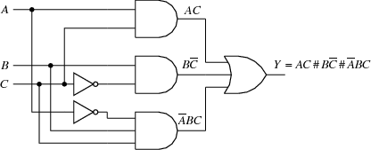
Fichier circuit_05.jps — Modifié le 3 Mai 2006 à 14 h 19

Source
%% source : reds.eivd.ch/download/manuels/ElecNum_T1_v10.pdf
uselogic
autocrop
-5 7 setxrange
-5 6 setxrange
30 setxunit
/logicUnit .25 def
/loadnodedict true def

/logicNInput 3 def
(A) node             %% declaration du noeud A
3 2 (OR) ccpict     %% cellule NOR en (0,1) (cc => plein centre)

/logicWireLength .75 def
(B) node
Ain1 1.5 add () (AND) clpict
(C) node
Ain1 () (AND) clpict
(D) node
/logicNInput 3 def
Ain1 1.5 sub () (AND) clpict

[Bout Ain2] ligne
[Dout Ain0] ligne

/logicWireLength .25 def
/logicUnit .2 def
(E) node
Cin0 () (INV) clpict
(F) node
Din2 (hadjust 5) (INV) clpict

/A {Bin1 exch pop -3.2 exch} def
/B {Cin1 exch pop -3.2 exch} def
/C {Cin0 exch pop -3.2 exch} def

[A Bin1] ligne
[B Cin1] ligne
[C Ein] ligne
[Fout Din2] ligne

/angleA 180 def
/angleB 90 def
Bin0 Ein (-*) pcangle

/angleB -90 def
Fin A .5 0 addv (-*) pcangle
Din0 C .7 0 addv (-*) pcangle
Din1 B 1 0 addv (-*) pcangle

setTimesItalic
   (A) A cltext
   (B) B cltext
   (C) C cltext
   (AC) Bout ultext
#tex# $B\overline C$
Cout ultexlabel
#tex# $\overline ABC$
Dout (3 0) ultexlabel
#tex# $Y = AC \, \# \, B\overline C \, \# \, \overline ABC$
Aout (-10 0) ubtexlabel