%@Auteur: François Meria\par
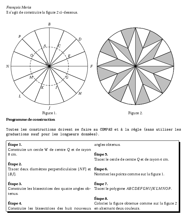
Il s'agit de construire la figure 2 ci-dessous.

\begin{multicols}{2}
\begin{center}
\psset{unit=0.5cm}
  \pspicture(-9,-9)(9,9)
  \pstGeonode[PointSymbol=none,PosAngle={135,180,0,90,-90}](0,0){Q}(-8,0){N}(8,0){F}(0,8){B}(0,-8){J}
  \pstGeonode[PointSymbol=none,PointName=none](4,0){T}
  \pstCircleOA{Q}{F}
  \pstCircleOA[linestyle=dashed]{Q}{T}
  \pstBissectBAC[PointSymbol=none]{F}{Q}{B}{D}
  \pstBissectBAC[PointSymbol=none,PosAngle=135]{B}{Q}{N}{P}
  \pstBissectBAC[PointSymbol=none,PosAngle=-135]{N}{Q}{J}{L}
  \pstBissectBAC[PointSymbol=none]{J}{Q}{F}{H}
  \pstBissectBAC[PointName=none,PointSymbol=none]{F}{Q}{D}{M_1}
  \pstBissectBAC[PointName=none,PointSymbol=none]{D}{Q}{B}{M_2}
  \pstBissectBAC[PointName=none,PointSymbol=none]{B}{Q}{P}{M_3}
  \pstBissectBAC[PointName=none,PointSymbol=none]{P}{Q}{N}{M_4}
  \pstBissectBAC[PointName=none,PointSymbol=none]{N}{Q}{L}{M_5}
  \pstBissectBAC[PointName=none,PointSymbol=none]{L}{Q}{J}{M_6}
  \pstBissectBAC[PointName=none,PointSymbol=none]{J}{Q}{H}{M_7}
  \pstBissectBAC[PointName=none,PointSymbol=none]{H}{Q}{F}{M_8}
  \pstInterLC[PointSymbol=none,PosAngleA=-100,PosAngleB=55]{Q}{M_1}{Q}{T}{M}{E}
  \pstInterLC[PointSymbol=none,PosAngleA=-80,PosAngleB=42]{Q}{M_2}{Q}{T}{K}{C}
  \pstInterLC[PointSymbol=none,PosAngleA=-100,PosAngleB=50]{Q}{M_3}{Q}{T}{I}{A}
  \pstInterLC[PointSymbol=none,PosAngleA=-90,PosAngleB=90]{Q}{M_4}{Q}{T}{G}{O}
  \psline(N)(F)
  \psline(B)(J)
  \pstBissectBAC[PointSymbol=none,PointName=none]{F}{Q}{B}{D}
  \pstBissectBAC[PointSymbol=none,PointName=none]{B}{Q}{N}{P}
  \pstBissectBAC[PointSymbol=none,PointName=none]{N}{Q}{J}{L}
  \pstBissectBAC[PointSymbol=none,PointName=none]{J}{Q}{F}{H}
  \pstBissectBAC[PointName=none,PointSymbol=none]{F}{Q}{D}{M_1}
  \pstBissectBAC[PointName=none,PointSymbol=none]{D}{Q}{B}{M_2}
  \pstBissectBAC[PointName=none,PointSymbol=none]{B}{Q}{P}{M_3}
  \pstBissectBAC[PointName=none,PointSymbol=none]{P}{Q}{N}{M_4}
  \pstBissectBAC[PointName=none,PointSymbol=none]{N}{Q}{L}{M_5}
  \pstBissectBAC[PointName=none,PointSymbol=none]{L}{Q}{J}{M_6}
  \pstBissectBAC[PointName=none,PointSymbol=none]{J}{Q}{H}{M_7}
  \pstBissectBAC[PointName=none,PointSymbol=none]{H}{Q}{F}{M_8}
  \put(-1.5,-10){Figure 1.}
  \endpspicture
\end{center}

\columnbreak

\begin{center}
\psset{unit=0.5cm}
  \pspicture(-9,-9)(9,9)
    \pscircle[fillstyle=solid,fillcolor=lightgray](0,0){8}
    \pstGeonode[PointSymbol=none,PosAngle={-90,180,0,90,-90},PointName=none](0,0){Q}(-8,0){N}(8,0){F}(0,8){B}(0,-8){J}
    \pstGeonode[PointSymbol=none,PointName=none](4,0){T}
    \pstCircleOA{Q}{F}
    \pstCircleOA[linestyle=dashed]{Q}{T}
    \pstBissectBAC[PointSymbol=none,PointName=none]{F}{Q}{B}{D}
    \pstBissectBAC[PointSymbol=none,PointName=none]{B}{Q}{N}{P}
    \pstBissectBAC[PointSymbol=none,PointName=none]{N}{Q}{J}{L}
    \pstBissectBAC[PointSymbol=none,PointName=none]{J}{Q}{F}{H}
    \pstBissectBAC[PointName=none,PointSymbol=none]{F}{Q}{D}{M_1}
    \pstBissectBAC[PointName=none,PointSymbol=none]{D}{Q}{B}{M_2}
    \pstBissectBAC[PointName=none,PointSymbol=none]{B}{Q}{P}{M_3}
    \pstBissectBAC[PointName=none,PointSymbol=none]{P}{Q}{N}{M_4}
    \pstBissectBAC[PointName=none,PointSymbol=none]{N}{Q}{L}{M_5}
    \pstBissectBAC[PointName=none,PointSymbol=none]{L}{Q}{J}{M_6}
    \pstBissectBAC[PointName=none,PointSymbol=none]{J}{Q}{H}{M_7}
    \pstBissectBAC[PointName=none,PointSymbol=none]{H}{Q}{F}{M_8}
    \pstInterLC[PointSymbol=none,PointName=none]{Q}{M_1}{Q}{T}{M}{E}
    \pstInterLC[PointSymbol=none,PointName=none]{Q}{M_2}{Q}{T}{K}{C}
    \pstInterLC[PointSymbol=none,PointName=none]{Q}{M_3}{Q}{T}{I}{A}
    \pstInterLC[PointSymbol=none,PointName=none]{Q}{M_4}{Q}{T}{G}{O}
    \pswedge[fillstyle=solid,fillcolor=white](Q){8}{22.5}{45}
    \pswedge[fillstyle=solid,fillcolor=white](Q){8}{67.5}{90}
    \pswedge[fillstyle=solid,fillcolor=white](Q){8}{112.5}{135}
    \pswedge[fillstyle=solid,fillcolor=white](Q){8}{157.5}{180}
    \pswedge[fillstyle=solid,fillcolor=white](Q){8}{202.5}{225}
    \pswedge[fillstyle=solid,fillcolor=white](Q){8}{247.5}{270}
    \pswedge[fillstyle=solid,fillcolor=white](Q){8}{292.5}{315}
    \pswedge[fillstyle=solid,fillcolor=white](Q){8}{337.5}{360}
    \pspolygon(A)(B)(C)(D)(E)(F)(G)(H)(I)(J)(K)(L)(M)(N)(O)(P)
    \psline[fillstyle=solid,fillcolor=lightgray](B)(C)(Q)
    \psline[fillstyle=solid,fillcolor=lightgray](P)(A)(Q)
    \psline[fillstyle=solid,fillcolor=lightgray](N)(O)(Q)
    \psline[fillstyle=solid,fillcolor=lightgray](L)(M)(Q)
    \psline[fillstyle=solid,fillcolor=lightgray](J)(K)(Q)
    \psline[fillstyle=solid,fillcolor=lightgray](H)(I)(Q)
    \psline[fillstyle=solid,fillcolor=lightgray](F)(G)(Q)
    \psline[fillstyle=solid,fillcolor=lightgray](D)(E)(Q)
    \psline[fillstyle=solid,fillcolor=white](B)(A)(Q)
    \psline[fillstyle=solid,fillcolor=white](P)(O)(Q)
    \psline[fillstyle=solid,fillcolor=white](N)(M)(Q)
    \psline[fillstyle=solid,fillcolor=white](L)(K)(Q)
    \psline[fillstyle=solid,fillcolor=white](J)(I)(Q)
    \psline[fillstyle=solid,fillcolor=white](H)(G)(Q)
    \psline[fillstyle=solid,fillcolor=white](F)(E)(Q)
    \psline[fillstyle=solid,fillcolor=white](D)(C)(Q)
    \psline(N)(F)
    \psline(B)(J)
    \pstBissectBAC[PointSymbol=none,PointName=none]{F}{Q}{B}{D}
    \pstBissectBAC[PointSymbol=none,PointName=none]{B}{Q}{N}{P}
    \pstBissectBAC[PointSymbol=none,PointName=none]{N}{Q}{J}{L}
    \pstBissectBAC[PointSymbol=none,PointName=none]{J}{Q}{F}{H}
    \pstBissectBAC[PointName=none,PointSymbol=none]{F}{Q}{D}{M_1}
    \pstBissectBAC[PointName=none,PointSymbol=none]{D}{Q}{B}{M_2}
    \pstBissectBAC[PointName=none,PointSymbol=none]{B}{Q}{P}{M_3}
    \pstBissectBAC[PointName=none,PointSymbol=none]{P}{Q}{N}{M_4}
    \pstBissectBAC[PointName=none,PointSymbol=none]{N}{Q}{L}{M_5}
    \pstBissectBAC[PointName=none,PointSymbol=none]{L}{Q}{J}{M_6}
    \pstBissectBAC[PointName=none,PointSymbol=none]{J}{Q}{H}{M_7}
    \pstBissectBAC[PointName=none,PointSymbol=none]{H}{Q}{F}{M_8}
    \put(-1.5,-10){Figure 2.}
  \endpspicture
\end{center}
\end{multicols}

\textbf{Programme de construction }\\

{\texttt{Toutes les constructions doivent se faire au COMPAS
et à la règle (sans utiliser les graduations sauf pour les longueurs données).}}\\

\shadowbox{
\begin{minipage}[c]{\textwidth}
\begin{multicols}{2}\setlength{\columnseprule}{0.5pt}
\textbf{\'Etape 1.}\\
Construire un cercle $\mathcal{C}$ de centre $Q$ et de rayon 8~cm.\\

\textbf{\'Etape 2.}\\
Tracer deux diamètres perpendiculaires $[NF]$ et $[BJ]$.\\

\textbf{\'Etape 3.}\\
Construire les bissectrices des quatre angles obtenus.\\

\textbf{\'Etape 4.}\\
Construire les bissectrices des huit nouveaux angles obtenus.\\

\textbf{\'Etape 5.}\\
Tracer le cercle de centre $Q$ et de rayon 4~cm.\\

\textbf{\'Etape 6.}\\
Nommer les points comme sur la figure 1.\\

\textbf{\'Etape 7.}\\
Tracer le polygone $ABCDEFGHIJKLMNOP$.\\

\textbf{\'Etape 8.}\\
Colorier la figure obtenue comme sur la figure 2 en alternant deux
couleurs.
\end{multicols}
\setlength{\columnseprule}{0pt}
\end{minipage}
}