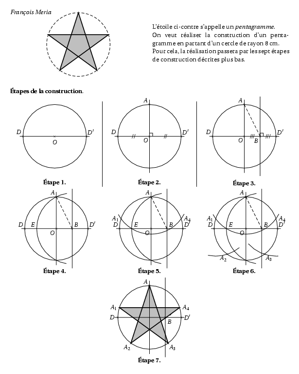
%@Auteur: François Meria\par
\begin{multicols}{2}
\begin{center}
\psset{unit=0.20cm}
    \pspicture(-11,-11)(11,7)
        \pstGeonode[PointSymbol=none,PosAngle={-135,135,45,135},PointName=none](0,0){O}(-10,0){D}(10,0){D'}(0,10){A}
        \pstCircleOA[linestyle=dashed]{O}{D}
        \pstGeonode[PointName=none,PointSymbol=none](0,-10){Z}
        \pstGeonode[PointSymbol=none,PosAngle=45,PointName=none](5,0){B}
        \pstGeonode[PointName=none,PointSymbol=none](5,11){T}(5,-11){T'}
        \pstInterLC[PointSymbol=none,PointName=none,PosAngle=45]{D}{D'}{B}{A}{E}{E'}
        \pstCurvAbsNode[PointName=none,PointSymbol=none]{B}{A}{M_1}{-80}
        \pstCurvAbsNode[PointName=none,PointSymbol=none]{B}{A}{M_2}{320}
        \pstCurvAbsNode[PointName=none,PointSymbol=none]{A}{E}{K_1}{-150}
        \pstCurvAbsNode[PointName=none,PointSymbol=none]{A}{E}{K_2}{430}
        \pstInterCC[PointSymbol=none,PosAngleA=180,PointName=none]{O}{D}{A}{E}{A_1}{A_4}
        \pstInterCC[PointSymbol=none,PointName=none,PosAngle=225]{O}{D}{A_1}{A}{A_2}{H}
        \pstInterCC[PointSymbol=none,PointName=none,PosAngle=-45]{O}{D}{A_4}{A}{R}{A_3}
        \pstCurvAbsNode[PointName=none,PointSymbol=none]{A_1}{A_2}{P_1}{-35}
        \pstCurvAbsNode[PointName=none,PointSymbol=none]{A_1}{A_2}{P_2}{25}
        \pstCurvAbsNode[PointName=none,PointSymbol=none]{A_4}{A_3}{Q_1}{-35}
        \pstCurvAbsNode[PointName=none,PointSymbol=none]{A_4}{A_3}{Q_2}{25}
        \pspolygon[fillstyle=solid,fillcolor=lightgray,linewidth=0.5mm](A)(A_2)(A_4)(A_1)(A_3)
    \endpspicture
\end{center}

\columnbreak

L'étoile ci-contre s'appelle un \textit{pentagramme}.\\
On veut réaliser la construction d'un pentagramme en partant d'un
cercle de rayon 8~cm.\\
Pour cela, la réalisation passera par les sept étapes de
construction décrites plus bas.
\end{multicols}

\textbf{\'Etapes de la construction}.

\begin{multicols}{3}\setlength{\columnseprule}{0.5pt}
%figure 1
\begin{center}
\psset{unit=0.20cm}
    \pspicture(-11,-11)(11,11)
        \pstGeonode[PointSymbol=x,PosAngle={-90,135,45}](0,0){O}(-10,0){D}(10,0){D'}
        \pstCircleOA{O}{D}
        \pstLineAB[nodesep=-1]{D}{D'}
    \endpspicture

\vskip 0.3cm

\textbf{\'Etape 1.}
\end{center}

%% figure 2
\begin{center}
\psset{unit=0.20cm}
    \pspicture(-11,-11)(11,11)
        \pstGeonode[PointSymbol=x,PosAngle={-135,135,45,135}](0,0){O}(-10,0){D}(10,0){D'}(0,10){A}
        \pstCircleOA{O}{D}
        \pstLineAB[nodesep=-1]{D}{D'}
        \pstGeonode[PointName=none,PointSymbol=none](0,-10){Z}
        \pstLineAB[nodesep=-1.5]{A}{Z}
        \pstRightAngle[RightAngleSize=1]{A}{O}{D'}
        \pstSegmentMark[SegmentSymbol=pstslashh]{D}{O}
        \pstSegmentMark[SegmentSymbol=pstslashh]{O}{D'}
    \endpspicture

\vskip 0.3cm

\textbf{\'Etape 2.}
\end{center}

%%% figure 3
\begin{center}
\psset{unit=0.20cm}
    \pspicture(-11,-11)(11,11)
        \pstGeonode[PointSymbol=x,PosAngle={-135,135,45,135}](0,0){O}(-10,0){D}(10,0){D'}(0,10){A}
        \pstCircleOA{O}{D}
        \pstLineAB[nodesep=-1]{D}{D'}
        \pstGeonode[PointName=none,PointSymbol=none](0,-10){Z}
        \pstLineAB[nodesep=-1.5]{A}{Z}
        \pstGeonode[PointSymbol=x,PosAngle=225](5,0){B}
        \pstGeonode[PointName=none,PointSymbol=none](5,11){T}(5,-11){T'}
        \pstLineAB[nodesep=-1.5]{T}{T'}
        \pstLineAB[linestyle=dashed]{A}{B}
        \pstRightAngle[RightAngleSize=1]{T}{B}{D'}
        \pstSegmentMark[SegmentSymbol=pstslashhh]{O}{B}
        \pstSegmentMark[SegmentSymbol=pstslashhh]{B}{D'}
    \endpspicture

\vskip 0.3cm

\textbf{\'Etape 3.}
\end{center}
\end{multicols}

\begin{multicols}{3}
%%%% figure 4
\begin{center}
\psset{unit=0.20cm}
    \pspicture(-11,-10)(10,11)
        \pstGeonode[PointSymbol=x,PosAngle={-135,135,45,135}](0,0){O}(-10,0){D}(10,0){D'}(0,10){A}
        \pstCircleOA{O}{D}
        \pstLineAB[nodesep=-1]{D}{D'}
        \pstGeonode[PointName=none,PointSymbol=none](0,-10){Z}
        \pstLineAB[nodesep=-1.5]{A}{Z}
        \pstGeonode[PointSymbol=x,PosAngle=45](5,0){B}
        \pstGeonode[PointName=none,PointSymbol=none](5,11){T}(5,-11){T'}
        \pstLineAB[nodesep=-1.5]{T}{T'}
        \pstLineAB[linestyle=dashed]{A}{B}
        \pstInterLC[PointSymbol=none,PointNameB=none,PosAngle=135]{D}{D'}{B}{A}{E}{E'}
        \pstCurvAbsNode[PointName=none,PointSymbol=none]{B}{A}{M_1}{-20}
        \pstCurvAbsNode[PointName=none,PointSymbol=none]{B}{A}{M_2}{160}
        \pstArcOAB{B}{M_1}{M_2}
    \endpspicture

\vskip 0.3cm

\textbf{\'Etape 4.}
\end{center}

%%%%% figure 5
\begin{center}
\psset{unit=0.20cm}
    \pspicture(-11,-10)(10,11)
        \pstGeonode[PointSymbol=x,PosAngle={-135,135,45,135}](0,0){O}(-10,0){D}(10,0){D'}(0,10){A}
        \pstCircleOA{O}{D}
        \pstLineAB[nodesep=-1]{D}{D'}
        \pstGeonode[PointName=none,PointSymbol=none](0,-10){Z}
        \pstLineAB[nodesep=-1.5]{A}{Z}
        \pstGeonode[PointSymbol=x,PosAngle=45](5,0){B}
        \pstGeonode[PointName=none,PointSymbol=none](5,11){T}(5,-11){T'}
        \pstLineAB[nodesep=-1.5]{T}{T'}
        \pstLineAB[linestyle=dashed]{A}{B}
        \pstInterLC[PointSymbol=none,PointNameB=none,PosAngle=45]{D}{D'}{B}{A}{E}{E'}
        \pstCurvAbsNode[PointName=none,PointSymbol=none]{B}{A}{M_1}{-20}
        \pstCurvAbsNode[PointName=none,PointSymbol=none]{B}{A}{M_2}{160}
        \pstArcOAB{B}{M_1}{M_2}
        \pstCurvAbsNode[PointName=none,PointSymbol=none]{A}{E}{K_1}{-35}
        \pstCurvAbsNode[PointName=none,PointSymbol=none]{A}{E}{K_2}{110}
        \pstArcOAB{A}{K_1}{K_2}
        \pstInterCC[PointSymbol=none,PosAngleA=180]{O}{D}{A}{E}{A_1}{A_4}
    \endpspicture

\vskip 0.3cm

\textbf{\'Etape 5.}
\end{center}

%%%%%% figure 6
\begin{center}
\psset{unit=0.20cm}
    \pspicture(-11,-10)(10,11)
        \pstGeonode[PointSymbol=x,PosAngle={-135,135,45,135}](0,0){O}(-10,0){D}(10,0){D'}(0,10){A}
        \pstCircleOA{O}{D}
        \pstLineAB[nodesep=-1]{D}{D'}
        \pstGeonode[PointName=none,PointSymbol=none](0,-10){Z}
        \pstLineAB[nodesep=-1.5]{A}{Z}
        \pstGeonode[PointSymbol=x,PosAngle=45](5,0){B}
        \pstGeonode[PointName=none,PointSymbol=none](5,11){T}(5,-11){T'}
        \pstLineAB[nodesep=-1.5]{T}{T'}
        \pstLineAB[linestyle=dashed]{A}{B}
        \pstInterLC[PointSymbol=none,PointNameB=none,PosAngle=45]{D}{D'}{B}{A}{E}{E'}
        \pstCurvAbsNode[PointName=none,PointSymbol=none]{B}{A}{M_1}{-20}
        \pstCurvAbsNode[PointName=none,PointSymbol=none]{B}{A}{M_2}{160}
        \pstArcOAB{B}{M_1}{M_2}
        \pstCurvAbsNode[PointName=none,PointSymbol=none]{A}{E}{K_1}{-35}
        \pstCurvAbsNode[PointName=none,PointSymbol=none]{A}{E}{K_2}{110}
        \pstArcOAB{A}{K_1}{K_2}
        \pstInterCC[PointSymbol=none,PosAngleA=180]{O}{D}{A}{E}{A_1}{A_4}
        \pstInterCC[PointSymbol=x,PointNameB=none,PosAngle=225]{O}{D}{A_1}{A}{A_2}{H}
        \pstInterCC[PointSymbol=x,PointNameA=none,PosAngle=-45]{O}{D}{A_4}{A}{R}{A_3}

        \pstCurvAbsNode[PointName=none,PointSymbol=none]{A_1}{A_2}{P_1}{-35}
        \pstCurvAbsNode[PointName=none,PointSymbol=none]{A_1}{A_2}{P_2}{25}
        \pstArcOAB{A_1}{P_1}{P_2}

        \pstCurvAbsNode[PointName=none,PointSymbol=none]{A_4}{A_3}{Q_1}{-35}
        \pstCurvAbsNode[PointName=none,PointSymbol=none]{A_4}{A_3}{Q_2}{25}
        \pstArcOAB{A_4}{Q_1}{Q_2}
    \endpspicture

\vskip 0.3cm

\textbf{\'Etape 6.}
\end{center}
\end{multicols}
\setlength{\columnseprule}{0pt}
%%%%%%% figure 7
\begin{center}
\psset{unit=0.20cm}
    \pspicture(-11,-10)(11,11)
        \pstGeonode[PointSymbol=x,PosAngle={-135,180,0,135}](0,0){O}(-10,0){D}(10,0){D'}(0,10){A}
        \pstGeonode[PointName=none,PointSymbol=none](0,-10){Z}
        \pstGeonode[PointSymbol=x,PosAngle=45](5,0){B}
        \pstGeonode[PointName=none,PointSymbol=none](5,11){T}(5,-11){T'}
        \pstInterLC[PointSymbol=none,PointNameB=none,PosAngle=45]{D}{D'}{B}{A}{E}{E'}
        \pstCurvAbsNode[PointName=none,PointSymbol=none]{B}{A}{M_1}{-20}
        \pstCurvAbsNode[PointName=none,PointSymbol=none]{B}{A}{M_2}{160}
        \pstCurvAbsNode[PointName=none,PointSymbol=none]{A}{E}{K_1}{-35}
        \pstCurvAbsNode[PointName=none,PointSymbol=none]{A}{E}{K_2}{110}
        \pstInterCC[PointSymbol=none,PosAngleA=180]{O}{D}{A}{E}{A_1}{A_4}
        \pstInterCC[PointSymbol=x,PointNameB=none,PosAngle=225]{O}{D}{A_1}{A}{A_2}{H}
        \pstInterCC[PointSymbol=x,PointNameA=none,PosAngle=-45]{O}{D}{A_4}{A}{R}{A_3}
        \pstCurvAbsNode[PointName=none,PointSymbol=none]{A_1}{A_2}{P_1}{-35}
        \pstCurvAbsNode[PointName=none,PointSymbol=none]{A_1}{A_2}{P_2}{25}
        \pstCurvAbsNode[PointName=none,PointSymbol=none]{A_4}{A_3}{Q_1}{-35}
        \pstCurvAbsNode[PointName=none,PointSymbol=none]{A_4}{A_3}{Q_2}{25}
        \pspolygon[fillstyle=solid,fillcolor=lightgray,linewidth=0.5mm](A)(A_2)(A_4)(A_1)(A_3)

        \pstCircleOA{O}{D}
        \pstLineAB[nodesep=-1]{D}{D'}
        \pstLineAB[nodesep=-1.5]{A}{Z}
        \pstLineAB[nodesep=-1.5]{T}{T'}
        \pstGeonode[PointSymbol=x,PosAngle=-45](5,0){B}
    \endpspicture

\vskip 0.3cm

\textbf{\'Etape 7.}
\end{center}